3d shapes created for simulation serve the purpose of bringing realism to a scene. It also helps identify everything in the scene easier. If for example all of the objects in a scene were simple shapes like cubes and circles it can be difficult to distinguish objects in the simulation.
Collision shapes vs Visual shapes
Simple shapes like cubes and spheres, better known as “primitives”, are often used as collision pieces. Collision shapes use simplified geometry compared to the visual mesh because they serve different purposes in simulations.
Collision models are important because they interact with the physics environment. They require less computation if they use primitive shapes.
Visual shapes are detailed meshes. These shapes are made with the goal of bringing realism to a simulated scene. These shapes are more dense in polygons and usually have textures attached to them. These shapes are what camera sensors pick up and are also what the viewer sees when viewing simulations.
Creating Models
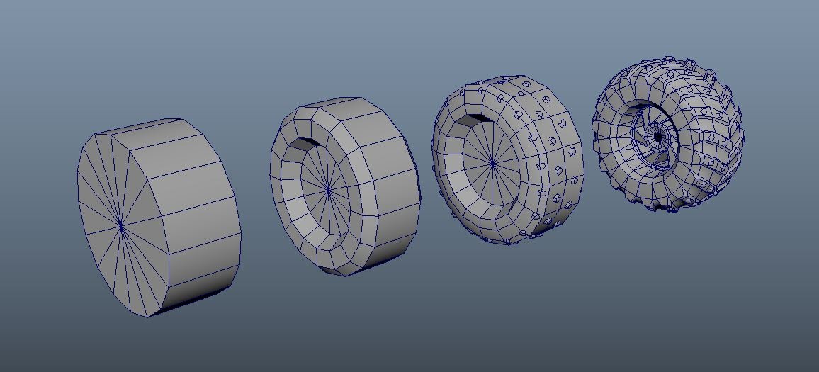
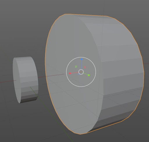
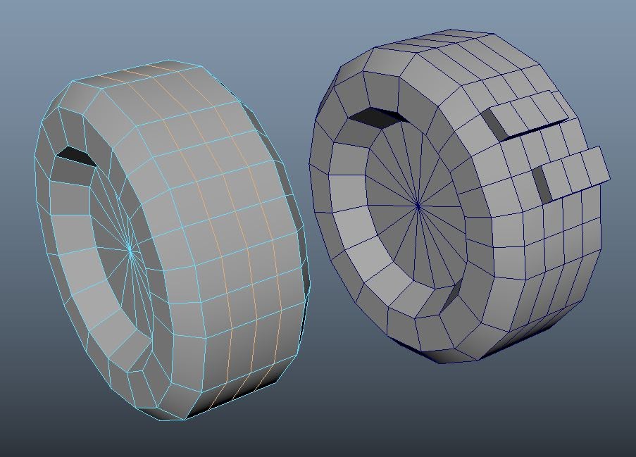
Blender has many tools to create simple/complex models. A great way to create complex objects is to start with something simple. In the example below we see a complex model created from a simple primitive. Although this is a great strategy for modeling, going from a simple mesh to a complex one usually requires a lot of tools to be used.
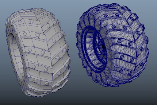
Because we used the example of the wheel above, I will be using that shape to go over my modeling workflow. I will also explain some of the tools and modifiers that I use. A basic understanding of the movement keys should be known prior to starting this tutorial: Recommended beginner guide
Create/add simple mesh
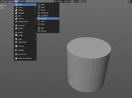
For this model cylinder mesh is used as a starting point. –> (Add>Mesh>Cylinder)
Having reference images of what you are planning to model can be a great help too, and is alway recommended.
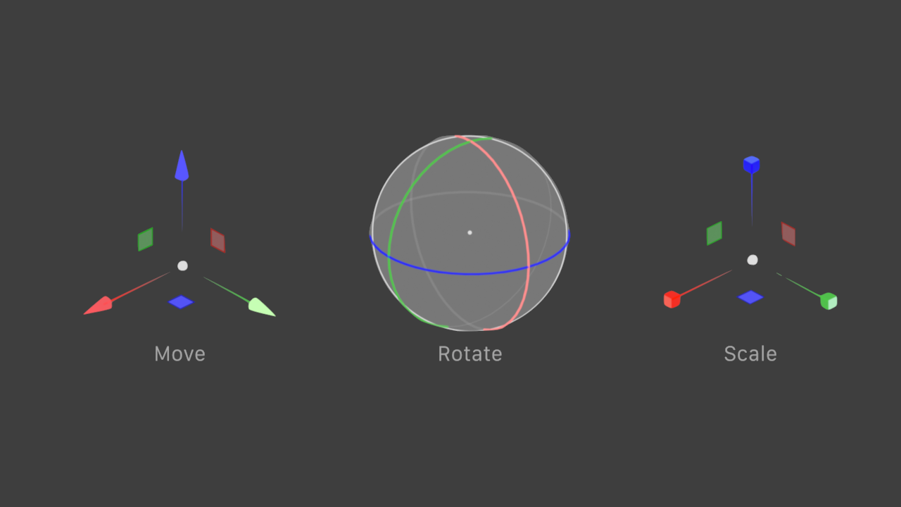
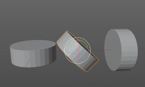
The move, rotate, and scale are used throughout most 3d modeling processes. These three actions are commonly known as the transform gizmos.
Oftentimes, problems after importing models into a program occur because of simple mistakes related to these gizmos. These problems are fairly common, but aren't hard to fix. Changing one of those attributes accordingly and exporting it out with the updates fixes most issues.
- Move Gizmo: allows you to change the location of an object along the x,y,z axis.
(Hotkey G)
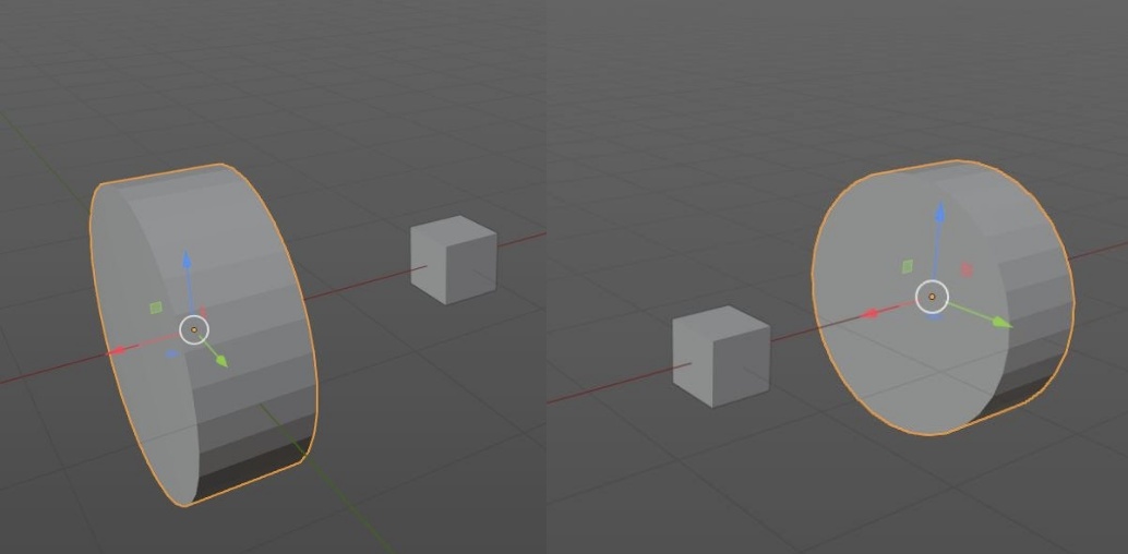
- Rotate Gizmo: allows you to rotate object orientation along the x,y,z axis
(Hotkey R)This was used to rotate the cylinder upright for the wheel.
- Scale Gizmo: allows you to scale an obj. Objects can also be scaled along a single axis if desired.
(Hotkey S)
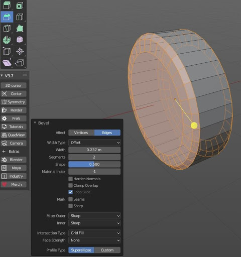
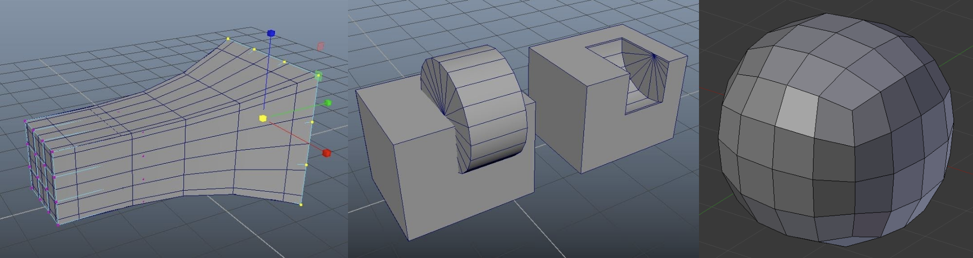
- Bevel: allow you to create curved/chamfered edges This was used to create the curved sides of the wheel.
- Extrude: adds additional geometry along a selected face/edges. The extrude tool can be used to push out a face or to push in one. Both examples are given here.
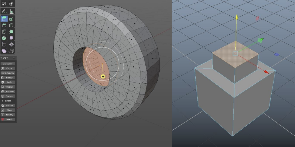
This was used to create the indents of the wheel.
(Mesh > Extrude > Extrude Region)
- Loop cut: allows you to split a face with a new looped edge. This then allows for more detailed manipulation of faces to take place.
This with a combination of the extrude tool you can make small ridges to your shape.
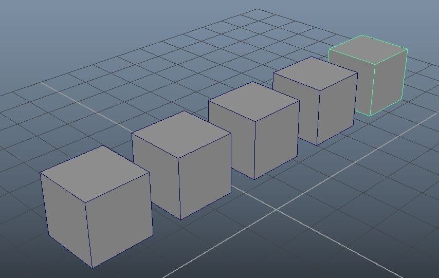
- Duplicate: allows you to make identical copies of a selected object.
- Other Modifiers: Some other commands that were used during a modeling process are: lattice functions,booleans, smooth, decimate.
More polygons less performance
Shapes are made out of polygons. The higher the polygons on a shape the more detailed it is. A shape with too many polygons can overcomplicate mesh editing or can make simulations run very slowly. This is why it is important to optimize a shape so that it keeps most of its details but without making the poly count too high.
If you find that your model is too dense to work with. The “decimate” command can be used to lower the polycount of said mesh, while still keeping its general shape.
Creating a complex model requires a good understanding of many tools in a 3d modeling program. They all serve their specific purposes and are extremely powerful. They have to be used on top of each other in different ways to get to an end result. The more you add/edit your shape the better it will look in the long run.
Exporting models
When you export a model for Gazebo, the .dae (COLLADA) file type is recommended. STL and OBJ files are also supported, but are less common for imports into Gazebo.
To export: select your shape and then File>Export>Collada(Default)(.dae)
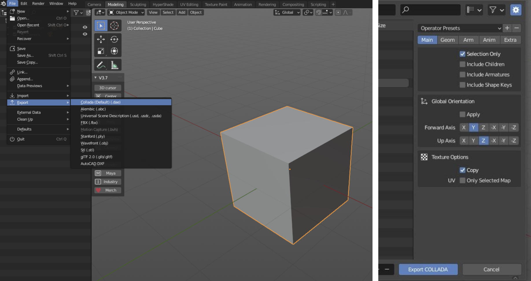
After you hit export in whatever file format you decide to go with, the "Blender File View" will appear. This is where you choose the location of your file. You can also choose how you want to export your model.
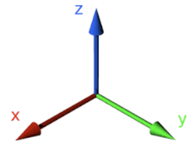
Double checking the “global Orientation” can save time and here you can quickly change the “Up Axis” to Z up. This is the standard orientation in Gazebo
Equally make sure that the If the shape is meant to stand on the ground, place the origin on the base, and make the model face X (Forward Axis)
Troubleshooting
There are a few things to take account of when creating a 3d shape for use in simulations. Making sure your scale and orientation are set to Gazebo standards can save you a lot of time.
- Check Scale/Location: If an imported shape is brought into Gazebo with the wrong units, it might be too big/small for the scene. Make sure that your modeling units are 1:1 with what is in Gazebo (Gazebo uses meters).
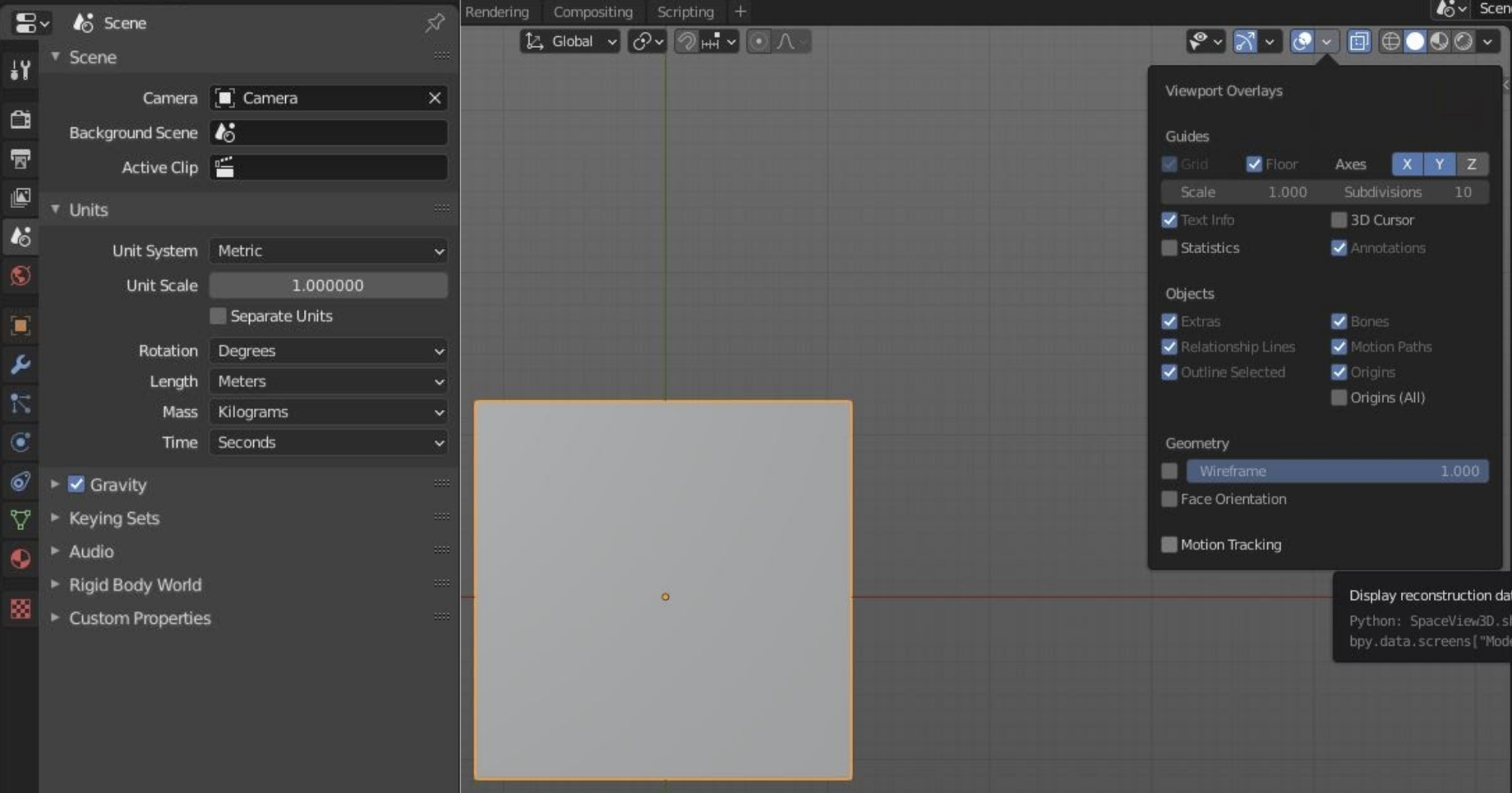
To change the units in Blender to match Gazebo go to “Scene Properties”. Change the “unit Systems” to Metric and change the “Length” to Meters.
To change the grid size go to “Show Overlays” and change the “Scale” amount.
- Check Pivot Point/Shape Origins:: When exporting a shape it is usually best practice to make sure that your model is in the middle of your grid
(0,0,0), unless said model is part of a bigger scene.
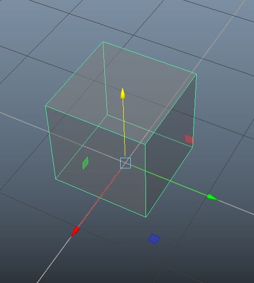
The Pivot Point of a shape is the point from which the shape moves, rotates, and scales from.
Not only do you need to make sure that your shape is in the right location prior to export, but you also need to make sure that the pivot points are in the right positions as well.
Complex shapes often have a child/parent relationship. This is when a smaller part of a shape is attached to a larger piece, but they have different pivot points.
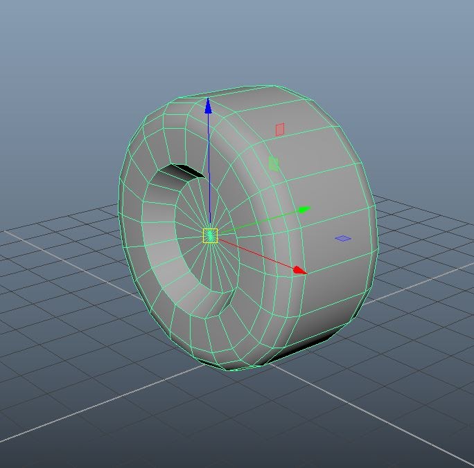
For example: The wheel used for this tutorial would be a child shape. It would “parented” to the body of a car. The pivot point of the wheel is in its center axis as shown, but the general pivots of the whole shape would be attached based on the parent shape, around the joint origin. When you export to Gazebo make sure that the whole shape is selected and that the main body is on the origin (0,0,0), and X Axis facing forward.